
Rebar Shop drawings - The Critical Role of Detail and Documentation
This is a highly significant subject.
Many detailers often do not pay sufficient attention to the installation aspect of the job.
They tend to overlook the fundamental purpose of Rebar Shop Drawings.
Our task involves creating Rebar Shop Drawings, which are essentially Rebar Placement drawings. These drawings serve as guides for laborers during the rebar installation process.
Our primary goal should be to create clear and easily understandable drawings for the laborers, rather than merely seeking approval from the engineer.
I will attempt to explain how laborers use these shop drawings, which should provide you with a better understanding of what a genuinely useful rebar shop drawing should resemble.
First, it's essential to put yourself in the shoes of the laborers to comprehend their perspective.
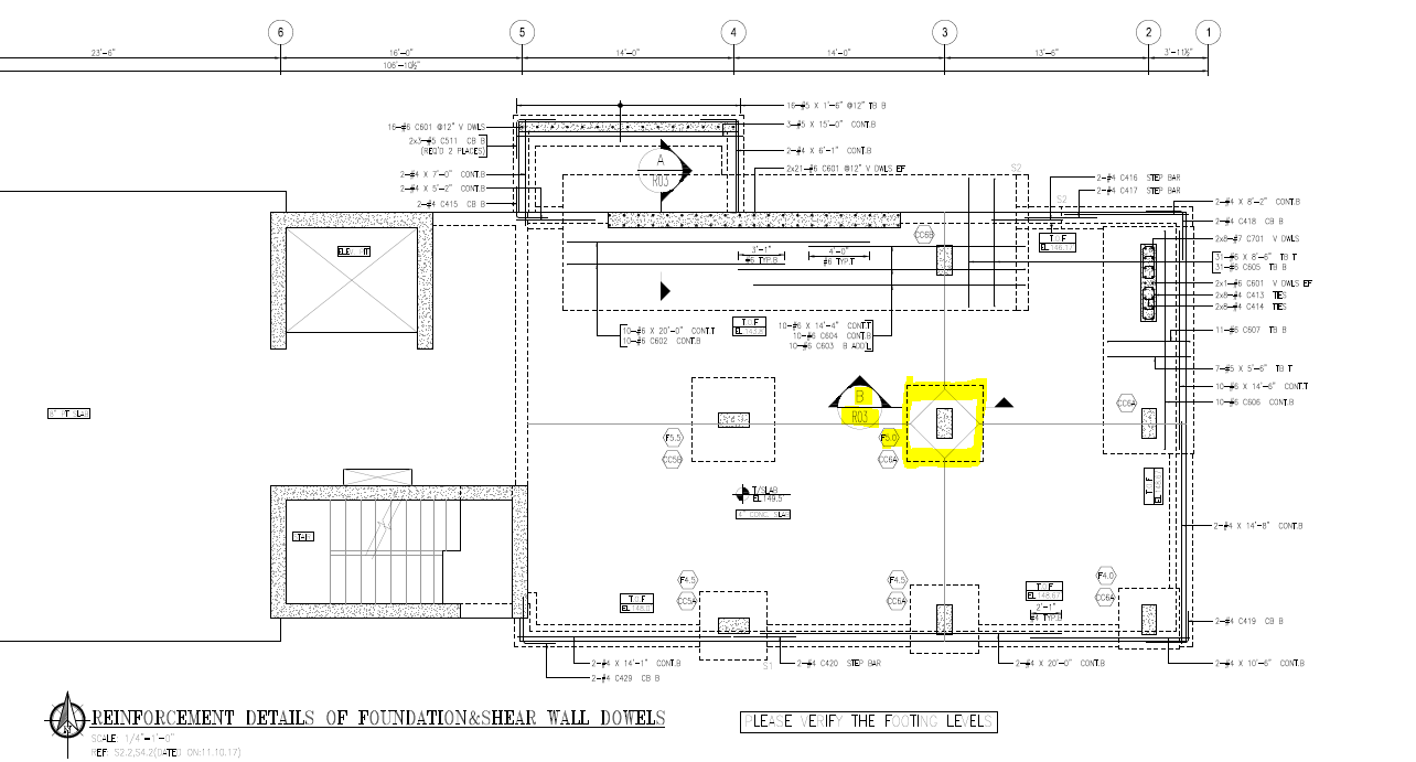
Let's imagine that we are a foreman for this project, and the supervisor has instructed us to construct the column footing labeled F5.0 as shown in the structural drawings below:

To begin, we first lay out the location of the footing. This requires us to mark Column Line 3 and Column Line B on the ground based on the points provided by the licensed surveyor.
A licensed surveyor arrives on-site to provide reference points and offers a drawing indicating the precise locations of these points. These surveyor points are typically marked on pieces of wood or wooden stakes, often accompanied by a note specifying the distance from the specific reference point.
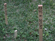
These reference markers are commonly referred to as surveyor stakes. While the image provided is not specific to this project, it illustrates the concept of surveyor points. In the image, you can see the surveyor point marked on top of short white wooden pieces, with wooden stakes placed on each side to indicate the distance from that point. To establish a straight line, a minimum of two reference points is necessary.
For instance, let's consider two surveyor stakes placed precisely at 20 feet and 30 feet away from Column Line 2, directly aligned with Column Line B. The distances between these stakes should be clearly indicated on the surveyor's plan and also marked on each stake itself.
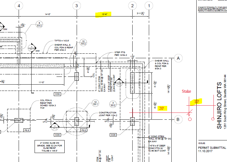
Now that we've established the 20' stake is located 20 feet away from Column Line 2, and Column Line 3 is positioned at 13 feet 6 inches from Column Line 2, we can determine that Column Line 3 is 33 feet 6 inches away from the surveyor stake. To confirm that we are precisely aligned with Column Line B, we utilize the 30' stake, which serves as the set-back line, in conjunction with the 20' stake to establish a straight line.
To achieve this, we typically employ a surveyor machine to create a straight line from the set-back point to Column Line 3. However, the specifics of using a surveyor machine to accomplish this task are a separate subject and a more detailed topic.
I'm emphasizing how challenging it can be to accurately transfer dimensions from a drawing to the actual ground.
Continuing with the process:
Once we've located the intersection of Column Line 3 and Column Line B, we need to move an additional 5 5/8 inches to accurately pinpoint the centerline of the column.
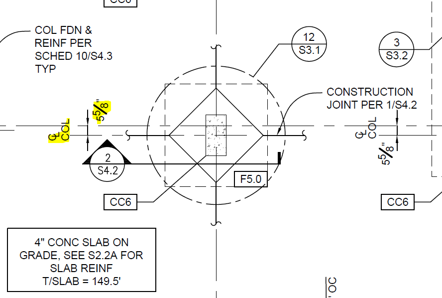
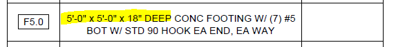
We've successfully identified the center point of the F5 footing. The next step is to determine the required size of the F5.0 footing, as specified in the footing schedule, which indicates a 5'x5' square and a depth of 18 inches.
Once we mark out sidelines of the footing on the ground, we ready to set the rebar.
Now we look at the rebar shop drawing,
We locate the F5.0 footing on the rebar shop drawing, and from there, we need to refer to Section B/R03.
Now, let's turn our attention to Section B/R03. This section detail is the most commonly used and should suffice for most detailers.
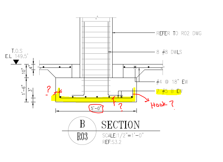
In Section B/R03, the rebar specifications indicate '7#5 Bottom each way.' However, this section doesn't provide several crucial pieces of information that are essential for our work:
- It doesn't specify the length of the rebar, which is crucial for cutting it to the correct size.
- It doesn't show the required clearance for the concrete, necessary for accurate rebar placement.
- There is no Bar Mark provided to determine the hook sizes.
In my search through the shop drawing, I stumbled upon the F5.0 footing on page R03A, which corresponds to Section C/R03-A. I realize there are no other F5.0 footings in these plans, so it's quite likely that there was an error in labeling the section as 'B/R03' instead of 'C/R03-A' by the detailer.
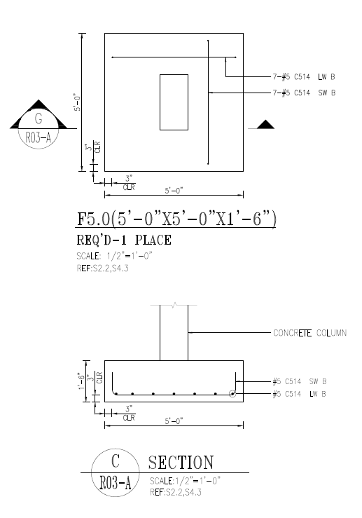
Indeed, such a simple mistake can lead to unnecessary delays. In the case of our foreman, he spent an additional 5-10 minutes searching for the correct detail. Now, imagine if there were four more laborers waiting for directions from the foreman. In such a scenario, we'd end up with a total loss of 40 minutes due to this simple error.
Moving forward:
Contractors often invest extra funds to have rebar fabricators pre-bend the rebar. Fabricators use automated machines to bend the rebar, bundle it, and attach appropriate tags. They rely on the bar list provided by the rebar detailer to accurately carry out the bending and cutting processes.
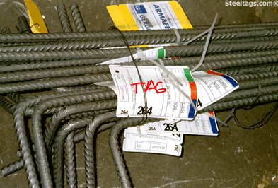
When we examine the tags,

Tags provide essential information, including the rebar's shape, the length of each leg, the Bar Mark, and the rebar's size.
Now, returning to the perspective of a foreman:
Assuming that all the required rebar has been delivered to the job site, our next task is to locate the specific rebar needed for the F5.0 footing.

So, our immediate challenge is to identify the C514 bar-marked rebar from the substantial pile of rebar. To understand what the rebar looks like, we must consult the bending schedule.
The trouble is, the location of the bending schedule can vary. Some detailers place it on the last page, while others choose different spots. In our case, we're currently on page R03, and there's no bending schedule here. We then find another bending schedule, but it doesn't mention C514.
With four workers waiting, and you, as the foreman, tasked with making the decision, it becomes evident that having a bending schedule on every page for the rebar shown on that page is crucial. This simple practice can make a significant difference between detailers.
Continuing:
Let's assume we've finally located the bending schedule and identified C514. According to the schedule, there are 14 of these rebar pieces with a size of 5, shape type 2, and a middle section (length of middle section B) of 4 feet 6 inches.
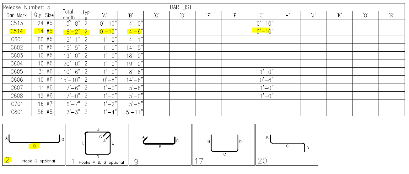
Now, with all the information available, we instruct the laborers to 'find me 14 C514 #5 bars, U shape, 4 feet 6 inches long at the middle.'
Labor now has the details required to locate C514 from the substantial pile of rebar. While the specific tag for C514 may not be immediately apparent, the knowledge of the rebar's size and length allows them to narrow down their search. They can measure the middle section to verify it matches the specified length and cross-reference it with the tag once located.
Additionally, you might want to explore the concept of 'Intelligent Bar Marks' which can significantly expedite the process of finding the right rebar. You can refer to the article I'll post for more information.
Once the laborers have located the 14 C514 rebar pieces, the next question is how to install them and determine the appropriate height above grade. It's also crucial to consider how to support the rebar. Unfortunately, these details are often lacking in Rebar Shop drawings, leaving the foreman and the team to rely on their expertise and best practices to address these aspects.

The use of concrete bricks instead of chairs on well-compacted grade makes a lot of sense, as it provides a stable and durable foundation for the rebar. Your suggestion to visually represent the use of concrete bricks under the rebar in drawings is a helpful idea for improving clarity and understanding in construction projects
Written by Kamil Cabuk , MS
Comments